- Hjem
- Products
- Beam-column connections
- Beam-column
- BSF 1100 kN, Beam-Column connection
Do you want more information and pricing?
1 / 3
Telescopic Beam Connection
BSF 1100 kN, Beam-Column connection
USP
- Corbel-free connection for beam-to-column and beam-to-beam applications
- Maximum vertical load capacity of 1100 kN
- Fast and safe installation with the steel knife retracted during erection
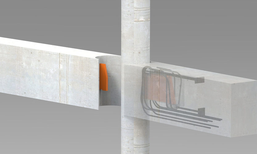
- Clean architectural finish with no visible supporting corbels
- Suitable for round and other non-standard column geometries
- Documented design guidance, reinforcement details and calculation tools
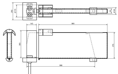
The connector is suitable for both beam-to-column and beam-to-beam applications. It has a maximum vertical load capacity of 1100 kN, a minimum column width of 400 mm and a minimum beam dimension of 310 x 590 mm.
Function and Design
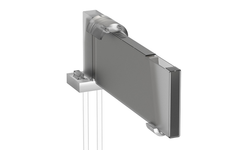
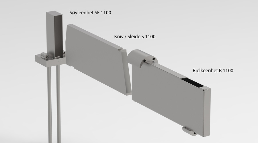
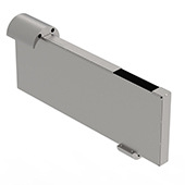
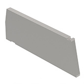
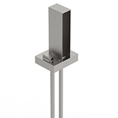
The BSF 1100 system consists of three main components: a beam unit cast into the supported beam, a column or beam-to-beam receiving unit cast into the supporting element, and a solid steel sliding knife that transfers the load between the units.
During erection, the knife is retracted and protected inside the beam unit. Once the beam is correctly positioned, the knife is extended into the receiving unit. The load is then transferred through the steel knife and into the specified anchoring reinforcement in the precast elements.
Materials and Finish
The main load-bearing components of the BSF 1100, including the blade and semi-circular bearing plates, are manufactured from S355 steel, with grade 8.8 threaded rods. The recess boxes are manufactured from thin sheet steel and supplied in standard finish.
Applications
BSF 1100 is designed for heavy-duty connections between precast beams and columns, beams and walls, or two beams. The corbel-free arrangement is particularly useful where architectural appearance, clear headroom, efficient formwork and flexible column geometry are important.
Installation and Fire Performance
The telescopic design supports fast and safe erection because the knife remains inside the beam unit until the beam is in position. After installation, the connection can be protected by the surrounding concrete and completed in accordance with the project-specific fire-protection design. The steel components have reaction to fire Class A1 according to EN 13501-1.
Documentation and Design
Technical memos cover capacities, main dimensions, reference levels, tolerances, torsion, expansion joints, seismic design proposals, reinforcement design and installation guidance. A dedicated BSF calculation tool is also available for structural design.
BSF products are manufactured under CE-marked production in accordance with EN 1090. The declared BSF 1100 vertical load capacity is 1100 kN, based on minimum concrete strength class C35/45 and project-specific reinforcement design.
Design
and reinforcement must be verified for the actual beam, supporting
element, loads, tolerances and project conditions using the current
technical documentation.
- Maximum vertical ULS load
- 1,100 kN
- Fire resistance with 25 mm concrete cover
- R60
- Minimum column width
- 400 mm
- Minimum beam width
- 310 mm
- Minimum beam height
- 590 mm
- Steel knife material
- S 355
- Half-round steel and steel plate
- S 355
- S 1100, kniv
- 132 kg
- B 1100, bjelkeenhet
- 34.7 kg
- SF 1100, søyleenhet
- 37.2 kg
- Anchorage reinforcement. Steel grade 500C shall be used
- Ø 12, Ø 16, Ø 25 mm
- Threaded bars to carry forces RHO and RHU. Bars are grade 8.8 steel
- M24
- Minimum concrete grade
- C35/45
 BSF 1100 k N søyle bjelke tegning