- Hjem
- Products
- Stair-landing connections
- Stair - landing connections
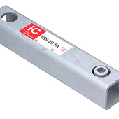
- TSS 20 FA, stair-landing connection
Do you want more information and pricing?
1 / 2
TSS 20 FA
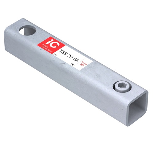
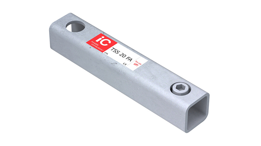
TSS 20 FA, stair-landing connection
Connection between the stair flight and landing, eliminating the need for a traditional corbel. Stepless height adjustment.
USP
- Stepless height adjustment
- Eliminates the need for a traditional corbel
- No shimming required
- Efficient installation on site
- Compact stair-to-landing connection
- Documented design basis
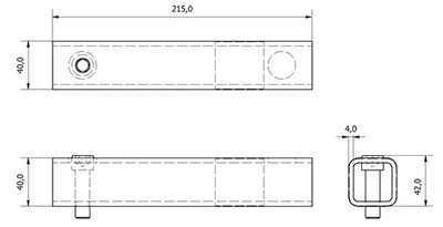
TSS 20 FA is a compact connection for connecting precast concrete stair flights to landings. The solution enables the connection to be installed without the need for a traditional corbel, providing a simpler and more efficient interface between the stair flight and landing.
The stepless height adjustment allows the stair flight to be adjusted to the required level during installation. This eliminates the need for shimming while making installation on site simpler and more efficient.

- Recommended maximum ULS load Fv,Ed [kN]
- 20 kN
- Minimum landing thickness full capacity
- 200 mm
- Weight black steel
- 0.93 kg
- Weight galvanized steel
- 0.97 kg
- Telescopic connection
- TSS
- Material
- Steel
- Inner tube material
- CFRHS 40 × 40 × 4, cold-formed S355
- Length of the bridge element
- 215 mm
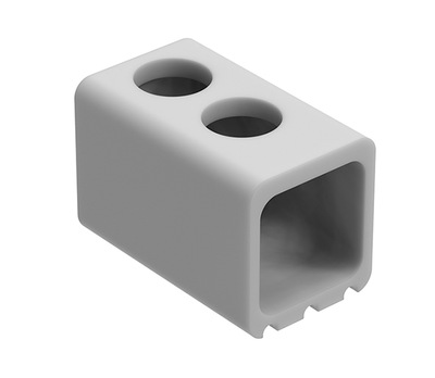
In accordance with TEK17, the following pre-accepted requirements apply to stair flights. See Memo 45:
Fire class | Requirement for stair flights |
Fire class 1 | – |
Fire class 2 | R30 [B30] |
Fire | R30 A2-s1,d0 [A30] |
TSS and RVK Connectors with Integrated Fire Protection
Invisible Connections’ TSS and RVK telescopic connectors provide loadbearing connections between precast concrete stairs or landings and the supporting stairwell walls.
Memo 45 covers solutions for buildings in fire classes 1, 2 and 3 and describes how fire protection must be considered in relation to both the connection itself and the interface with the stairwell wall.
A key principle of the solution is grouting around the connection. Following installation, the recess around the connector is filled with cementitious grout, providing a mineral cover between the steel components and the fire-exposed surface.
The principle is comparable to the fire protection provided to reinforcement embedded in concrete, where the distance between the fire-exposed surface and the steel helps protect the steel components from elevated temperatures during a fire.
R Classification and Minimum Cover
R denotes loadbearing capacity under fire conditions, while the number indicates the period of fire resistance in minutes. This use of R as the criterion for loadbearing capacity is consistent with the BS EN 13501-2 classification system.
Adequate cover to the loadbearing steel components is therefore an important part of the fire protection solution for IC connectors.
Fire resistance | Minimum cover “C” |
R30 | 15 mm |
R60 | 25 mm |
R90 | 35 mm |
R120 | 45 mm |
When installing TSS and RVK connectors, there is normally a 20–30 mm air gap between the precast concrete element and the stairwell wall.
The interface with the wall and any required fire stopping must be detailed and installed in accordance with the project-specific fire strategy.
Requirements determined by the project fire strategy
The required fire resistance depends on the building's fire class and on how the staircase forms part of the overall fire strategy.
For stair flights, the pre-accepted requirements shown above are R30 for fire class 2 and R30 A2-s1,d0 for fire class 3.
Higher fire resistance requirements may apply to certain structural arrangements. This may, for example, be relevant where the staircase is not located within a separate stairwell but is exposed within the fire compartment itself. In such cases, a higher fire resistance classification, such as R60, may be required.
The applicable fire resistance requirement must be determined by the responsible fire engineer for the individual project.
Connection and Fire Protection as an Integrated Solution
With Invisible Connections’ TSS and RVK telescopic connectors, the loadbearing connection of precast concrete stairs and landings is combined with a straightforward approach to fire protection.
Once the connection is grouted following installation, the loadbearing steel components are provided with the required mineral cover as an integral part of the completed construction.
The final fire resistance requirements and detailing must be determined and documented for each individual project by the responsible designer. Interfaces with adjacent construction, any required fire stopping and the final installation must comply with the project's fire strategy.
Laboratory tested in accordance with EN 17823
A staircase is more than a load-bearing structure. Every footstep generates vibrations that can travel through the connections and into the surrounding building structure. Effective acoustic decoupling between the stair flight, landing and wall is therefore essential to limit the transmission of impact sound.
To document the acoustic performance of our solutions, Invisible Connections has carried out laboratory testing in accordance with EN 17823, the European standard for the laboratory measurement of impact sound insulation of stairs and stair isolating elements.
The standard provides a common method for documenting and comparing acoustic performance. The results can, among other applications, be used as input data when calculating the expected impact sound levels in buildings in accordance with EN ISO 12354-2.
Independent laboratory testing at STEP
The testing was carried out by STEP GmbH at a specialised acoustic stair test facility in Jettingen, Germany.
During the test, precast concrete landings were installed using four IC connections to the reference wall. An air gap of approximately 20 mm was maintained between the landing and the wall.
The test configuration is designed to minimise unwanted flanking transmission and provide controlled measurement conditions. Impact sound was generated using a standardised tapping machine positioned at four different locations on the landing. The reference wall was additionally excited using an impact hammer at twelve positions.
The measurements were carried out in accordance with the methodology specified in EN 17823, together with relevant measurement and evaluation methods from EN ISO 10140-3 and EN ISO 717-2, among others.
Tested at different load levels
The acoustic performance of the connections was investigated under different loads. Using a hydraulic press, the load on the landing was increased incrementally, with loads per TSS/RVK connection ranging from 2.7 kN to 34.6 kN. This allowed the test to document how acoustic performance is affected as the connection and elastomer operate under different load levels.
Documented results
The laboratory test demonstrates a clear reduction in impact sound transmission.
For the isolated solutions, the weighted normalised impact sound pressure level, Lₙ,w, was measured, among other parameters. The results for the individual IC products are presented under Technical Data on the respective product pages.
EN 17823 also uses ΔLw,landing, which describes the improvement provided by the connection between the landing and the wall, including the impact sound isolating element, compared with direct excitation of the reference wall.
In addition, ΔL*w,landing is stated, where the isolated solution is compared with a rigidly connected reference landing.
These values provide acoustic consultants and designers with documented data for assessing and calculating impact sound performance in buildings.
Resilient acoustic decoupling
IC solutions use elastomeric material for vibration isolation to limit the transmission of structure-borne sound between the concrete stair or landing and the surrounding structure.
The profiled IC elements allow the elastomer to deform under load and recover its shape when the load is reduced. At the same time, a sufficient damping area is important to achieve the required acoustic performance.
Invisible Connections applies a design principle with a recommended damping area of 200–250 mm² per kN of ultimate load.
EN 17823 and European impact sound requirements
EN 17823 is a test standard, not a common European requirement specifying maximum impact sound levels in buildings. Specific requirements for completed buildings are established through national building regulations and standards and vary between countries, building types and applications.
EN 17823 instead provides a common European method for measuring, documenting and comparing the acoustic performance of stairs and stair-isolating connections.
This enables documented product data to be used as a basis for acoustic design and for assessing solutions against national impact sound requirements.
From laboratory testing to the finished building
Laboratory testing in accordance with EN 17823 provides documented data on the acoustic performance of IC connections. This gives acoustic consultants, precast manufacturers and contractors a more reliable basis for selecting and designing solutions where effective control of impact sound is essential.
 Tegning